Overview
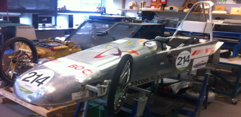
This project was completed in fulfillment of the Gold CREST award from November 2013 to July 2014. The CREST Award involves making an original contribution to a STEM field of study. It requires a minimum of 70 hours of work, time management, investigative skills, and report writing technique.
The goal of the project was to make a tachometer for my school’s electric race car. The following aims were set:
- Research existing ways of measuring rotational speed.
- Design and make a working prototype circuit on a breadboard, capable of measuring rotational speed and velocity.
- Test the accuracy of the prototype and make improvements as required.
- Create the final product on a printed circuit board (PCB).
- Test the accuracy of the final product, and calculate the percentage error.
- Demonstrate the product’s capabilities at the Regional Big Bang Convention in Duxford.
Design
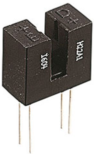
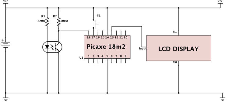
After researching components, a photointerrupter (light gate) was used as the sensor. This used an infrared LED that activated a phototransistor when the path between the two components weren’t interrupted. This set up was used to produce a square wave signal when a rotating disc with slits was placed between the components. By tying the collector of the phototransistor high through a 100Ω resistor, the collector output would be high when the gate was free and low when the gate was obstructed.
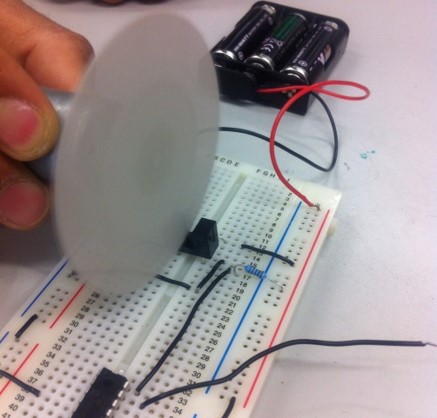
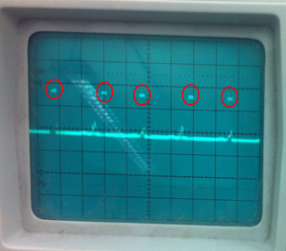
A PICAXE microcontroller was used to receive this signal and calculate the rotational speed. Code was written in the BASIC programming language, shown below:
symbol RPS = w0      ;w0 is the counts in one second = RPS
symbol RPM = w1      ;w1 is the counts in one minute = RPM
symbol MPM = w2      ;w2 is the distance travelled in one minutes in meters
symbol KPH = w3      ;w3 is the speed in kph
symbol LCD = B.7     ;the pin B.7 is now called LCD
symbol INP = C.1     ;the pin C.1 is now called INP (Input)

;this program is for 4 holes in the spinning disc
;1.5m is the wheel circumference

init:
pause 500            ;waits for LCD to initialise
goto main            ;go to label "main"

main:
count INP, 1000, RPS ;count pulses in 1 second
RPM = RPS * 15       ;multiply this by 15 to find RPM, due to 4 holes
MPM = RPM * 3/2      ;multiply RPM by 1.5m to find distance travelled per minute
KPH = MPM * 6/100    ;multiply distance travelled in 1 minute by 60, then by 1000 to get kph
serout LCD,N2400,(254,1, 254,128,#RPM,"rpm", 254,192,#KPH,"kph")
;clears display, sends rpm value and the text "rpm" to the display, and kph value and text “kph” to the display
RPS=0                ;resets variable RPS
RPM=0                ;resets variable RPM
MPM=0                ;resets variable RPH
KPH=0                ;resets variable KPH
goto main            ;loops back to start
The following circuit diagram was used to create the prototype circuit on a breadboard and the PCB design:
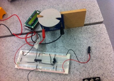
To test the prototype, we compared the LCD reading to the frequency of a stroboscope which was matched to the motor’s rotational speed.

Production
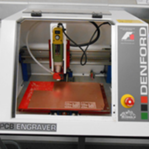
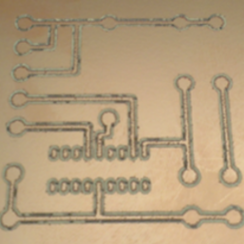
The PCB was made using an engraver to drill away the surface layer of copper. A separate board was made for the photointerrupter so that it could be mounted to the car’s rear wheel, with the main board being housed inside the car.
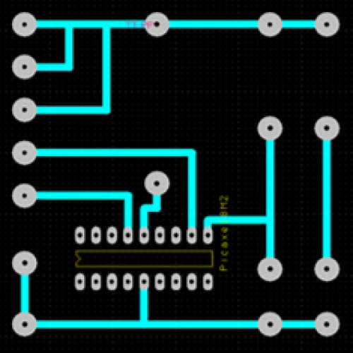
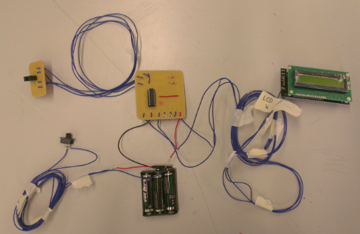
Crimp clips were used to connect the main board with the photointerrupter board and the LCD display. This was done so that the three parts could be installed separately in the three areas of the car, and then connected afterwards.
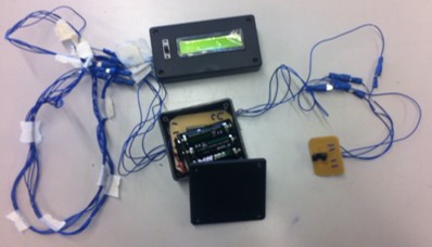
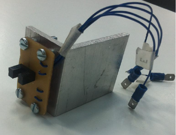
The photointerrupter PCB was mounted onto a metal bracket, which was then mounted to the exterior of the car body. Holes were drilled into the wheel’s disc to create the signal.
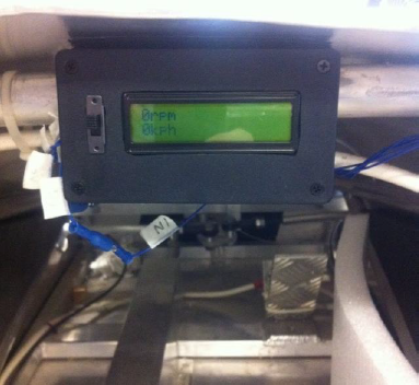
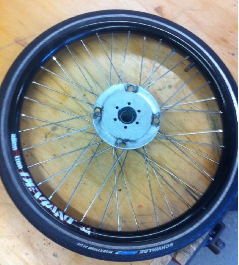
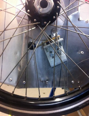
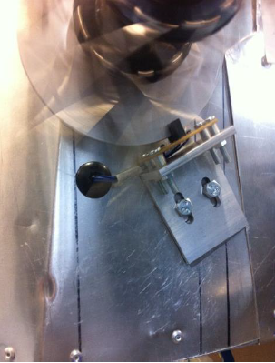
Testing and Results
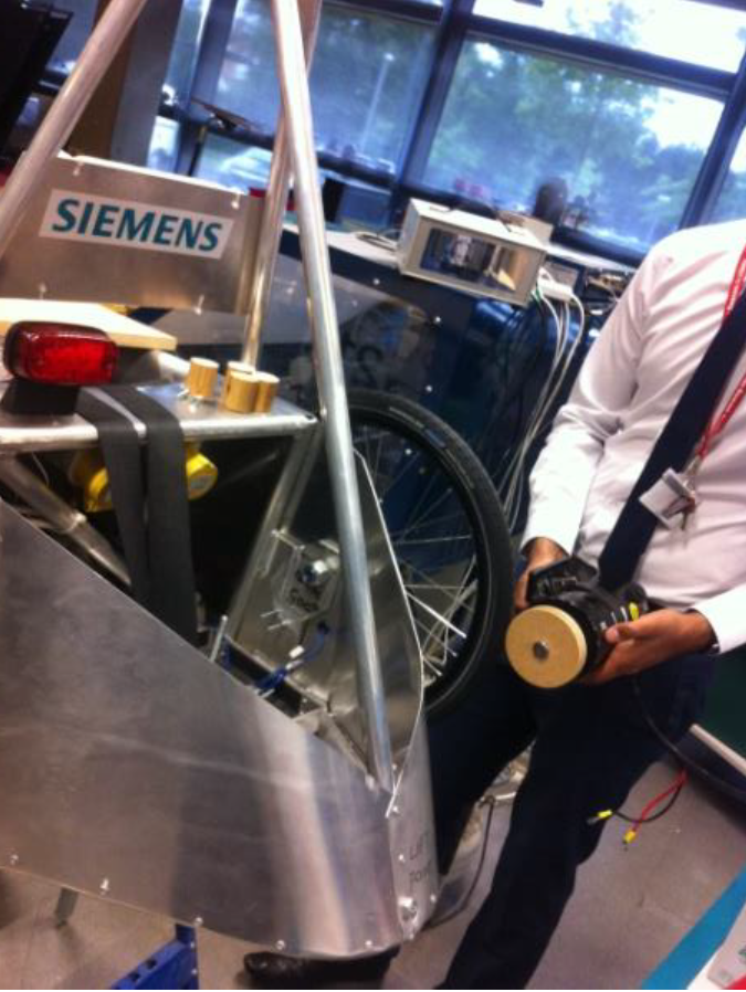
As the car wasn’t operating at the time, a 12V car battery with a wooden disc lined with elastic bands was used to spin the rear wheel with the tachometer attached.
A stroboscope was used again for testing, with a white mark on the wheel used to match the wheel’s rotational speed with the stroboscope frequency.
The stroboscope reading was an average of 4.15Hz, which equates to an RPM of 249. The tachometer reading was 255rpm.
By using two car batteries in series to increase the speed and provide another result, with a stroboscope reading of 7.95Hz equalling an RPM of 477, the tachometer reading was 480.
Taking these two readings and calculating an average percentage error resulted in an error of 1.49%.
Showcase
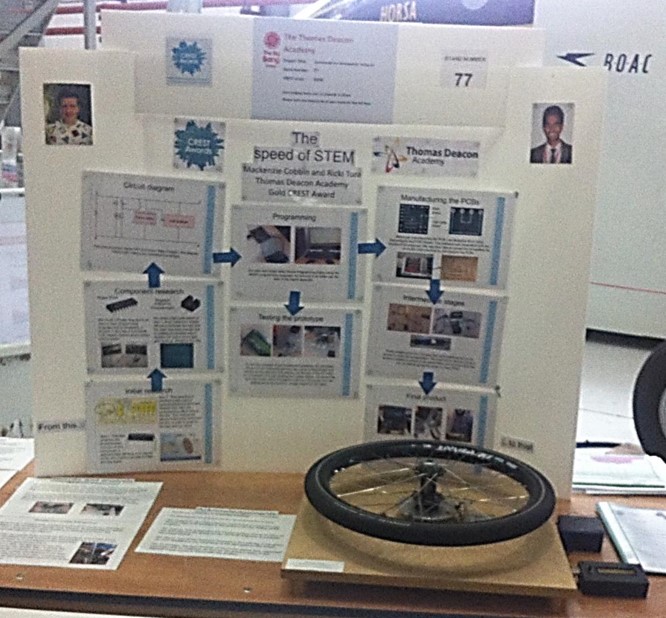
Upon completion, an accompanying report was produced on the project. This work was also presented to an engineer from Perkins Engines, as well as multiple presentations in school assemblies.
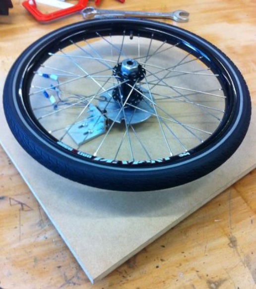
The project was also moved onto a portable rig to showcase at the regional Big Bang Fair, where it was ranked as “Highly recommended” by the judging panel.
For more information on the project, as well as the suggestions for further improvement, the full report is available to view below.